Voltage Domain Configuration
Hardware Configuration
Each project must fill out this table to ensure that the actual hardware connections match the software configuration. It is imperative to confirm the match before compiling the firmware:
| IO domain | Actual Voltage Used | Configurable Voltage | Voltage Source | Remarks |
|---|---|---|---|---|
| PMUIO1 | 3.3V | Fixed | Group with PMU | |
| PMUIO2 | 3.3V | 1.8/3.3 | LDO6 | |
| VCCIO1 | 3.3V | 1.8/3.3 | LDO4/VCCIO_ACODEC | Group with 809Codec |
| VCCIO2 | 1.8V | 1.8/3.3 | BUCK5 | Group with EMMC |
| VCCIO3 | 3.3V | 1.8/3.3 | LDO5/VCCIO_SD | Group with SD card |
| VCCIO4 | 1.8V | 1.8/3.3 | BUCK5 | Group with BT/WIFI |
| VCCIO5 | 3.3V | 1.8/3.3 | VCC3V3_SYS | Group with PCIE |
| VCCIO6 | 1.8V | 1.8/3.3 | BUCK5 | Group with GMAC |
| VCCIO7 | 3.3V | 1.8/3.3 | VCC3V3_SYS |
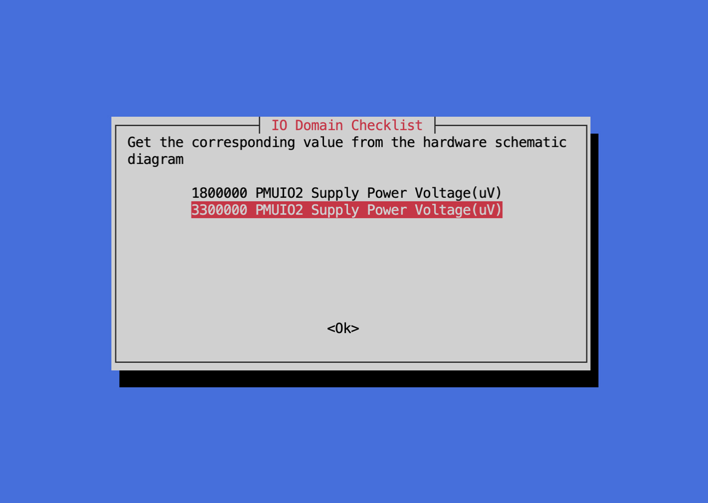
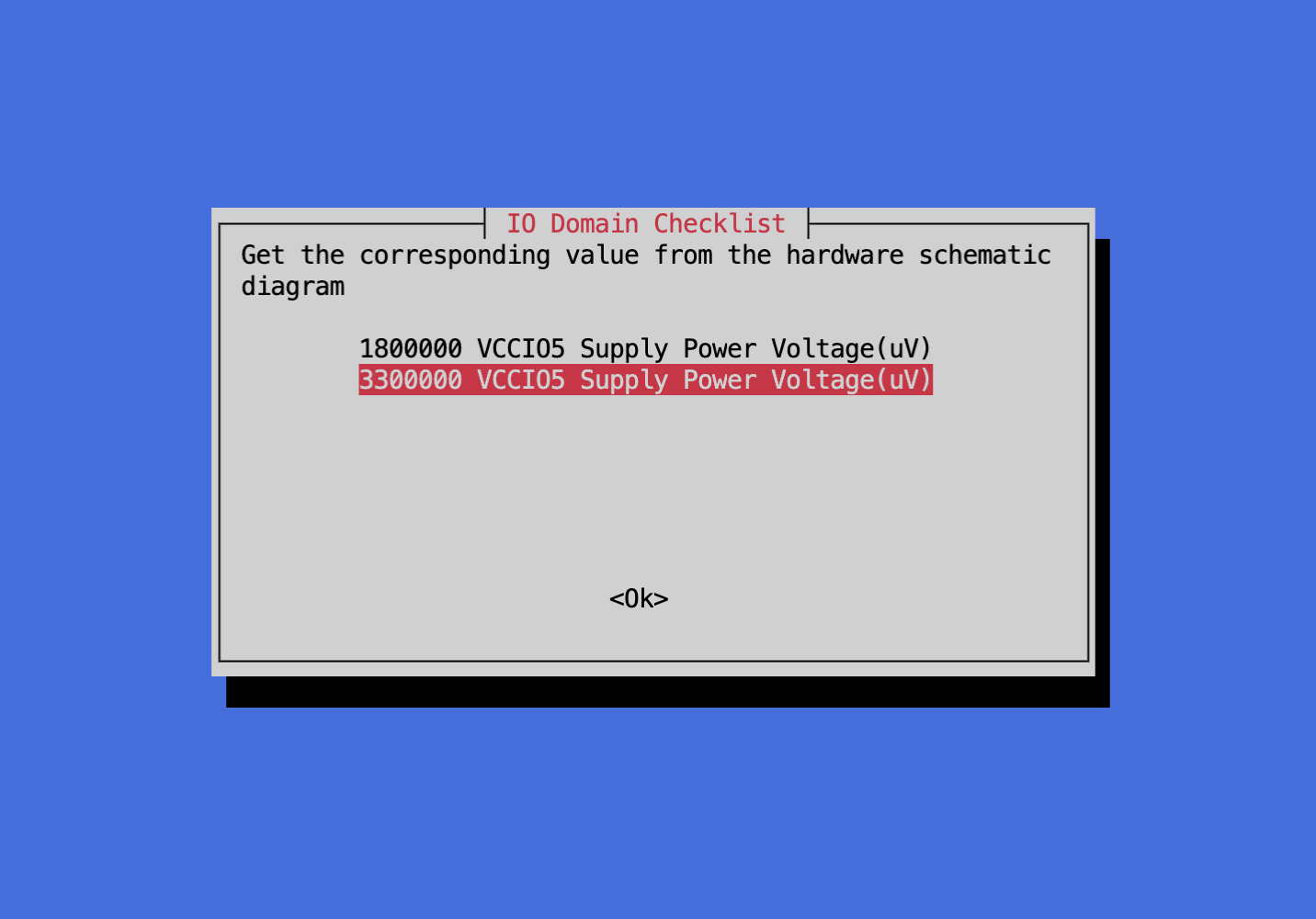
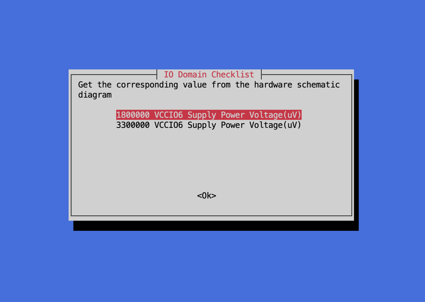
The first compilation will prompt you to configure the voltage domain, and the options are as follows:
PMUIO2:3.3V
VCCIO1:3.3V

VCCIO3:3.3V

VCCIO4:1.8V

VCCIO5:3.3V
VCCIO6:1.8V
VCCIO7:3.3V

DTS Configuration
File path: kernel/arch/arm64/boot/dts/rockchip/rk3568-evb.dtsi
&pmu_io_domains {
        status = "okay";
        pmuio2-supply = <&vcc3v3_pmu>;
        vccio1-supply = <&vccio_acodec>;
        vccio3-supply = <&vccio_sd>;
        vccio4-supply = <&vcc_1v8>;
        vccio5-supply = <&vcc_3v3>;
        vccio6-supply = <&vcc_1v8>;
        vccio7-supply = <&vcc_3v3>;
};
VCCIO Description
VCCIO Power Supply
If
VCCIO2is powered by1.8V,then theFLASH_VOL_SELpin must be kept high. The chip will automatically configure VCCIO2 to1.8Vmode based onFLASH_VOL_SEL=Logic high;If
VCCIO2is powered by3.3V, then theFLASH_VOL_SELpin must be kept low. The chip will automatically configure VCCIO2 to3.3Vmode based onFLASH_VOL_SEL=Logic low;If the power voltage supplied to
VCCIO2and theFLASH_VOL_SELdo not satisfy the above relationship, functions will be abnormal (such as unable to boot normally) or the IO may be damaged.
Software Voltage Configuration
When the hardware IO level is connected to
1.8V, the software voltage configuration must also be set to1.8V. If it is mistakenly configured to3.3V, the IO functions of this power domain will be abnormal;When the hardware IO level is connected to
3.3V, the software voltage configuration must also be set to3.3V. If it is mistakenly configured to1.8V, it will cause the IO of this power domain to be over-voltage, and the IO will be damaged if it works for a long time.
Configuration in Code
In the
RK3568_AIoT_REF_SCHreference diagram, theVCCIO3power domain IO is by default allocated forSD Cardfunction, The working modes of theSD Cardare:SD2.0 modeandSD3.0 mode; the IO level ofSD2.0 modeis3.3V, and the IO level ofSD3.0 modeis1.8V;In actual operation, it defaults to working in
SD2.0mode, that is,3.3VIO. If the inserted card supportsSD3.0, after negotiation, the IO level will switch to1.8VIO, and then switch to the rate of runningSD3.0;In the reference diagram, the
VCCIO3IO power is supplied byRK809-5 LDO5(network name isVCCIO_SD), which defaults to3.3V. According to the working mode of theSD Card,RK3568will configure the output voltage ofRK809-5 LDO5through I2C0.For example, the default configuration of the IO domain in
rk3568-evb.dtsiisvccio3-supply = <&vccio_sd>;The related configuration of
sdmmc0is as follows:
&sdmmc0 {
    max-frequency = <150000000>;
    supports-sd;
    bus-width = <4>;
    cap-mmc-highspeed;
    cap-sd-highspeed;
    disable-wp;
    sd-uhs-sdr104;
    vmmc-supply = <&vcc3v3_sd>;
    vqmmc-supply = <&vccio_sd>;
    pinctrl-names = "default";
    pinctrl-0 = <&sdmmc0_bus4 &sdmmc0_clk &sdmmc0_cmd &sdmmc0_det>;
    status = "okay";
};
To support the full
SD Cardfunction, this configuration is sufficient. The software will automatically switch the IO voltage and the correspondingIO domainvoltage mode according to theSD Cardmode.If there is no need to work in
SD3.0 mode, and it only needs to be fixed inSD2.0 mode(evenSD3.0 cardswill only work inSD2.0 mode),such as when using a discrete power supply, and you want to save the circuit that switches from3.3Vto1.8V, the hardwareVCCIO3 IOpower supply will be modified toVCC_3V3,and the software needs to make the following changes: TheIO domainconfiguration is changed tovccio3-supply = <&vcc_3v3>;The related configuration of
sdmmc0is modified as follows:
&sdmmc0 {
    max-frequency = <150000000>;
    supports-sd;
    bus-width = <4>;
    cap-mmc-highspeed;
    cap-sd-highspeed;
    disable-wp;
    vmmc-supply = <&vcc3v3_sd>;
    vqmmc-supply = <&vcc_3v3>;
    pinctrl-names = "default";
    pinctrl-0 = <&sdmmc0_bus4 &sdmmc0_clk &sdmmc0_cmd &sdmmc0_det>;
    status = "okay";
};
It is necessary to remove
sd-uhs-sdr104. If not removed, it will run inSD3.0 mode, and high-speed cards will fail to read.If the
VCCIO3power domain IO is allocated to other functions, such asUART5、UART6functions, then follow the note Software Voltage Configuration