Interface Definition
Overall Interface Definition
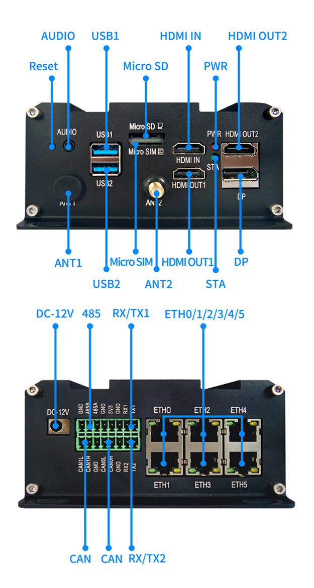
The LPM3588 offers a rich set of interfaces, detailed as follows:
| Silkscreen | Device Node | Remarks |
|---|---|---|
| AUDIO | Play audio files | |
| USB1 | Type-A USB3.0 host | |
| USB2 | Burning port | |
| HDMIIN | /dev/video40 | HDMI input, supports up to 4K@30fps resolution |
| HDMI1 | card0-HDMI-A-1 | HDMI output, supports up to 4K@60fps |
| HDMI2 | card0-HDMI-A-2 | HDMI output, supports up to 4K@60fps |
| DP | card0-DP-2 | DP output, supports up to 4K@60fps |
| CAN1 | can0 | CAN bus |
| CAN2 | can1 | CAN bus |
| UART1 | /dev/ttyS6 | Serial port, default baud rate 9600 |
| UART2 | /dev/ttyS7 | Serial port, default baud rate 9600 |
| RS485 | /dev/ttyS0 | Serial port, default baud rate 9600 |
| ETH0 | eth8 | Gigabit network card |
| ETH1 | eth9 | Gigabit network card |
| ETH2 | eth6 | Gigabit network card |
| ETH3 | eth7 | Gigabit network card |
| ETH4 | eth4 | Gigabit network card |
| ETH5 | eth5 | 100M network card |
| WIFI | wlan0 | 2.4/5GHz |
| PWR LED | Power indicator light | |
| SIM | 4G/5G Dialing | |
| STA LED | work2 | STA light |
| RTC | /dev/rtc0 | RTC clock |
AUDIO Usage
Use the first sound card’s first device to play the 001.wav file.
aplay -D hw:0,0 001.wav
• -D hw:0,0 specifies the playback device, hw:0,0 is card 0 device 0, which is the first sound card’s first device.
• 001.wav specifies the audio file, wav is the file format, 001 is the file name.
HDMIIN Usage
HDMI input is an interface that can receive external HDMI signals and convert them into MIPI signals. LPB3588 provides an HDMI input corresponding to the /dev/video40 device. Before using the HDMI input, you need to ensure that the HDMI device is connected correctly and that the resolution and frame rate settings are consistent.
Refer to 《HDMIIN》
HDMI/DP Explanation
The xrandx command can be used to check the current HDMI connection:
neardi@3588:~$ xrandr
Screen 0: minimum 320 x 200, current 1920 x 1080, maximum 16384 x 16384
HDMI-1 connected primary 1920x1080+0+0 (normal left inverted right x axis y axis) 0mm x 0mm
   1920x1080     60.00*+  60.00    50.00    30.00    24.00
   4096x2160     24.00
   3840x2160     30.00    25.00    24.00
   1920x1080i    60.00    50.00
   1280x720      60.00    60.00    50.00    50.00    30.00    24.00
   720x576       50.00    50.00
   720x480       59.94    59.94    59.94
HDMI-2 disconnected (normal left inverted right x axis y axis)
DP-1 disconnected (normal left inverted right x axis y axis)
Complete Node Definitions:
HDMI1:/sys/devices/platform/display-subsystem/drm/card0/card0-HDMI-A-1/
HDMI2:/sys/devices/platform/display-subsystem/drm/card0/card0-HDMI-A-2/
DP:/sys/devices/platform/display-subsystem/drm/card0/card0-DP-2/
CAN Usage
CAN is a bus standard used to enable communication between devices. The LPA3588 provides two CAN interfaces, corresponding to can0 and can1 devices. Before using CAN, ensure that the CAN device is correctly connected and the baud rate and other parameters are set consistently. The default firmware includes using candump and cansend tools for sending and receiving message tests. If the tools are not available, they can be downloaded from github.
# Turn off the can0 device at both sending and receiving ends
ip link set can0 down
# Set the bitrate at both sending and receiving ends
ip link set can0 up type can bitrate 1000000 dbitrate 3000000 fd on
# Execute candump at the receiving end, blocking waiting for messages
candump can0
# Execute cansend at the sending end, sending messages
cansend can0 123#1122334455667788
More commands:
1. ip link set canX down               // Turn off the CAN device;
2. ip link set canX up                 // Turn on the CAN device;
3. ip -details link show canX          // Show detailed information of the CAN device;
4. candump canX                        // Receive data sent by the CAN bus;
5. ifconfig canX down                  // Turn off the CAN device for configuration;
6. ip link set canX up type can bitrate 1000000 // Set the CAN baud rate
7. conconfig canX bitrate + baud rate;
8. canconfig canX start                // Start the CAN device;
9. canconfig canX ctrlmode loopback on // Loopback test;
10. canconfig canX restart             // Restart the CAN device;
11. canconfig canX stop                // Stop the CAN device;
12. canecho canX                       // Check the status of the CAN bus;
13. cansend canX --identifier=ID+data  // Send data;
14. candump canX --filter=ID:mask      // Use a filter to receive data matching the ID
UART Usage
The serial port is a common communication interface used for serial communication with external devices. The LPM3588 provides multiple serial ports, each corresponding to different device nodes. Before using the serial port, ensure that the port is correctly connected and the baud rate and other parameters are set consistently.
The RS485 device file is /dev/ttyS0. Run the following command on the development board device:
Send a string to the host:
echo "neardi RS485 test..." > /dev/ttyS0
The host’s serial terminal will receive the string “neardi RS485 test…”. The development board receives data:
Receive a string sent by the host:
cat /dev/ttyS0
Similarly, the device files for UART1 and UART2 are /dev/ttyS6 and /dev/ttyS7.
ETH Explanation
You can check the IP address via the debug serial port, ssh, or adb, for example:
neardi@3588:~$ ifconfig -a
enP2p33s0: flags=4163<UP,BROADCAST,RUNNING,MULTICAST>  mtu 1500
        inet 192.168.1.65  netmask 255.255.255.0  broadcast 192.168.1.255
        inet6 fe80::7df7:e74d:497e:345d  prefixlen 64  scopeid 0x20<link>
        ether 62:ea:fb:ca:95:e7  txqueuelen 1000  (Ethernet)
        RX packets 2548  bytes 210938 (210.9 KB)
        RX errors 0  dropped 0  overruns 0  frame 0
        TX packets 338  bytes 46899 (46.8 KB)
        TX errors 0  dropped 0 overruns 0  carrier 0  collisions 0
        device interrupt 140  base 0xd000
Wi-Fi Explanation
Check the current Wi-Fi model with the following commands:
cat /sys/bus/sdio/devices/mmc2\:0001\:1/vendor
cat /sys/bus/sdio/devices/mmc2\:0001\:1/device
0x02d00xaae8 is AP6275S,0x024c0xb852 is RTL8852
LED Explanation
Complete nodes:
SYS LED:cat /sys/devices/platform/leds/leds/work1/brightness
STA LED:cat /sys/devices/platform/leds/leds/work2/brightness
RTC Clock
LPA3588 uses HYM8563 as RTC clock.
How to change the RTC clock to ‘2018-11-11 12:00:00’
#Turn off the Network Time Protocol (NTP) service so that the RTC clock is not affected by network time
timedatectl set-ntp false
#Set the RTC clock time to November 11, 2018, at 12:00:00
timedatectl set-time '2018-11-11 12:00:00'
#Synchronize the RTC clock time to the system clock to keep the system clock and RTC clock consistent, can be added in /etc/init.d/rockchip.sh
hwclock --hctosys