Interface Definition
Overall Interface Definition
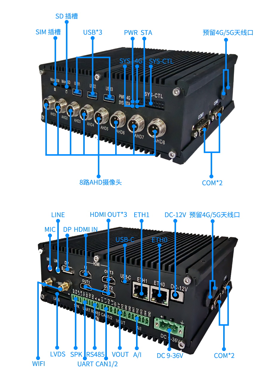
The LPA3588 offers a rich set of interfaces, detailed as follows:
| Silkscreen | Device Node | Remarks |
|---|---|---|
| MIC | Input sound, record audio files | |
| LINE | Play audio files | |
| DP | card0-DP-2 | DP output, supports up to 4K@60fps |
| HDMIIN | /dev/video22 | HDMI input, supports up to 4K@30fps resolution |
| HDMI1 | card0-HDMI-A-1 | HDMI output, supports up to 4K@60fps |
| HDMI2 | card0-HDMI-A-2 | HDMI output, supports up to 4K@60fps |
| HDMI3 | card0-DSI-1 | HDMI output, supports up to 4K@30fps |
| Type-C | Can switch USB and DP signals | |
| ETH0 | eth0 | Gigabit network card |
| ETH1 | eth1 | Gigabit network card |
| WIFI | wlan0 | 2.4/5GHz |
| SPK | gpio125 | GPIO, output mode, not controllable |
| RS485 | /dev/ttyS0 | Serial port, default baud rate 9600 |
| UART1 | /dev/ttyS6 | Serial port, default baud rate 9600 |
| UART2 | /dev/ttyS7 | Serial port, default baud rate 9600 |
| CAN1 | can0 | CAN bus |
| CAN2 | can1 | CAN bus |
| VOUT 12V | gpio42 | GPIO, output mode, power supply for peripherals |
| VOUT 5V | gpio42 | GPIO, output mode, power supply for peripherals |
| VOUT 3V3 | gpio42 | GPIO, output mode, power supply for peripherals |
| A/I IN1 | in_voltage4_raw | Analog input, for connecting some industrial sensors |
| A/I IN2 | in_voltage2_raw | Analog input, for connecting some industrial sensors |
| A/I IN3 | in_voltage6_raw | Analog input, for connecting some industrial sensors |
| A/I IN4 | in_voltage7_raw | Analog input, for connecting some industrial sensors |
| COM1 | /dev/ttysWK2 | Serial port RS232, default baud rate 9600 |
| COM2 | /dev/ttysWK0 | Serial port RS232, default baud rate 9600 |
| COM3 | /dev/ttysWK1 | Serial port RS232, default baud rate 9600 |
| COM4 | /dev/ttysWK3 | Serial port RS232, default baud rate 9600 |
| USB1 | Type-A USB3.0 host | |
| USB2 | Type-A USB3.0 host | |
| USB3 | Type-A USB3.0 host | |
| SYS-CTL | Debug&Key | Product Manual J22 |
| PWR LED | Power indicator light | |
| 4G LED | 4G indicator light 4G/5G Dialing | |
| SYS LED | work1 | System light |
| STA LED | work2 | STA light |
| AHD1 | /dev/video11 | Supports 1280x720@25/30HZ, 1920x1080@25/30HZ |
| AHD2 | /dev/video12 | Supports 1280x720@25/30HZ, 1920x1080@25/30HZ |
| AHD3 | /dev/video13 | Supports 1280x720@25/30HZ, 1920x1080@25/30HZ |
| AHD4 | /dev/video14 | Supports 1280x720@25/30HZ, 1920x1080@25/30HZ |
| AHD5 | /dev/video3 | Supports 1280x720@25/30HZ, 1920x1080@25/30HZ |
| AHD6 | /dev/video2 | Supports 1280x720@25/30HZ, 1920x1080@25/30HZ |
| AHD7 | /dev/video1 | Supports 1280x720@25/30HZ, 1920x1080@25/30HZ |
| AHD8 | /dev/video0 | Supports 1280x720@25/30HZ, 1920x1080@25/30HZ |
| RTC | /dev/rtc0 | RTC clock |
MIC Usage
Use the following command to record audio files, supporting formats such as wav, mp3, etc.
Record dual-channel 16-bit little-endian audio at a sampling rate of 48000Hz, then save it as a 001.wav file.
arecord -Dhw:0,0 -r48000 -f S16_LE -c2 > 001.wav
• -Dhw:0,0 specifies the recording device, 0,0 is card 0 device 0, which is the first sound card’s first device.
• -r48000 specifies the sampling rate in Hz, 48000 means 48000 samples per second.
• -f S16_LE specifies the sample format, S16_LE means signed 16-bit little-endian format, each sample point occupies 2 bytes, with the low byte first and the high byte last.
• -c2 specifies the number of channels, 2 means stereo.
• > 001.wav specifies the output file, > redirects standard output to a file, 001.wav is the file name, wav is the file format.
LINE Usage
Use the first sound card’s first device to play the 001.wav file.
aplay -D hw:0,0 001.wav
• -D hw:0,0 specifies the playback device, hw:0,0 is card 0 device 0, which is the first sound card’s first device.
• 001.wav specifies the audio file, wav is the file format, 001 is the file name.
HDMI/DP Explanation
The xrandx command can be used to check the current HDMI connection:
neardi@3588:~$ xrandr
Screen 0: minimum 320 x 200, current 1920 x 1080, maximum 16384 x 16384
HDMI-1 connected primary 1920x1080+0+0 (normal left inverted right x axis y axis) 0mm x 0mm
   1920x1080     60.00*+  60.00    50.00    30.00    24.00
   4096x2160     24.00
   3840x2160     30.00    25.00    24.00
   1920x1080i    60.00    50.00
   1280x720      60.00    60.00    50.00    50.00    30.00    24.00
   720x576       50.00    50.00
   720x480       59.94    59.94    59.94
HDMI-2 disconnected (normal left inverted right x axis y axis)
DSI-1 connected 1920x1080+0+0 (normal left inverted right x axis y axis) 0mm x 0mm
   1920x1080     60.00*+
DP-1 disconnected (normal left inverted right x axis y axis)
Complete Node Definitions:
HDMI1:/sys/devices/platform/display-subsystem/drm/card0/card0-HDMI-A-1/
HDMI2:/sys/devices/platform/display-subsystem/drm/card0/card0-HDMI-A-2/
HDMI3:/sys/devices/platform/display-subsystem/drm/card0/card0-DSI-1/
DP:/sys/devices/platform/display-subsystem/drm/card0/card0-DP-2/
HDMIIN Usage
HDMI input is an interface that can receive external HDMI signals and convert them into MIPI signals. The LPA3588 provides one HDMI input. Before using the HDMI input, ensure that the HDMI device is correctly connected and the resolution and frame rate settings are consistent.
Refer to 《HDMIIN》
ETH Explanation
You can check the IP address via the debug serial port, ssh, or adb, for example:
neardi@3588:~$ ifconfig -a
enP2p33s0: flags=4163<UP,BROADCAST,RUNNING,MULTICAST>  mtu 1500
        inet 192.168.1.65  netmask 255.255.255.0  broadcast 192.168.1.255
        inet6 fe80::7df7:e74d:497e:345d  prefixlen 64  scopeid 0x20<link>
        ether 62:ea:fb:ca:95:e7  txqueuelen 1000  (Ethernet)
        RX packets 2548  bytes 210938 (210.9 KB)
        RX errors 0  dropped 0  overruns 0  frame 0
        TX packets 338  bytes 46899 (46.8 KB)
        TX errors 0  dropped 0 overruns 0  carrier 0  collisions 0
        device interrupt 140  base 0xd000
Wi-Fi Explanation
Check the current Wi-Fi model with the following commands:
cat /sys/bus/sdio/devices/mmc2\:0001\:1/vendor
cat /sys/bus/sdio/devices/mmc2\:0001\:1/device
0x02d00xaae8 is AP6275S,0x024c0xb852 is RTL8852
UART Usage
The serial port is a common communication interface used for serial communication with external devices. The LPA3588 provides multiple serial ports, each corresponding to different device nodes. Before using the serial port, ensure that the port is correctly connected and the baud rate and other parameters are set consistently.
The RS485 device file is /dev/ttyS0. Run the following command on the development board device:
Send a string to the host:
echo "neardi RS485 test..." > /dev/ttyS0
The host’s serial terminal will receive the string “neardi RS485 test…”. The development board receives data:
Receive a string sent by the host:
cat /dev/ttyS0
Similarly, the device files for UART1 and UART2 are /dev/ttyS6 and /dev/ttyS7.
CAN Usage
CAN is a bus standard used to enable communication between devices. The LPA3588 provides two CAN interfaces, corresponding to can0 and can1 devices. Before using CAN, ensure that the CAN device is correctly connected and the baud rate and other parameters are set consistently. The default firmware includes using candump and cansend tools for sending and receiving message tests. If the tools are not available, they can be downloaded from github.
# Turn off the can0 device at both sending and receiving ends
ip link set can0 down
# Set the bitrate at both sending and receiving ends
ip link set can0 up type can bitrate 1000000 dbitrate 3000000 fd on
# Execute candump at the receiving end, blocking waiting for messages
candump can0
# Execute cansend at the sending end, sending messages
cansend can0 123#1122334455667788
More commands:
1. ip link set canX down               // Turn off the CAN device;
2. ip link set canX up                 // Turn on the CAN device;
3. ip -details link show canX          // Show detailed information of the CAN device;
4. candump canX                        // Receive data sent by the CAN bus;
5. ifconfig canX down                  // Turn off the CAN device for configuration;
6. ip link set canX up type can bitrate 1000000 // Set the CAN baud rate
7. conconfig canX bitrate + baud rate;
8. canconfig canX start                // Start the CAN device;
9. canconfig canX ctrlmode loopback on // Loopback test;
10. canconfig canX restart             // Restart the CAN device;
11. canconfig canX stop                // Stop the CAN device;
12. canecho canX                       // Check the status of the CAN bus;
13. cansend canX --identifier=ID+data  // Send data;
14. candump canX --filter=ID:mask      // Use a filter to receive data matching the ID
VOUT Usage
The VOUT interface is an interface that can provide power for external devices. The LPA3588 provides three VOUT interfaces, which output voltages of 12V, 5V and 3.3V respectively. Use a multimeter to measure the voltage and current of the VOUT 3.3V interface, which should be 3.3V and no more than 1A.
echo 42 > /sys/class/gpio/export;
echo out > /sys/class/gpio/gpio42/direction;
#Turn on VOUT function
echo 1 > /sys/class/gpio/gpio42/value;
#Turn off VOUT function
echo 0 > /sys/class/gpio/gpio42/value;
A/I Usage
Analog input is an interface that can detect the voltage or current of external devices. The LPA3588 provides four analog inputs, each corresponding to different device nodes. Before using analog input, ensure that the external device is correctly connected and the voltage or current range meets the requirements.
To test the analog input, use the following commands to read the value of the analog input:
Voltage value(V)=15/4096 * Reading value;
Current value(MA)=30/4096 * Reading value;
#Read the value of A/I IN1
cat /sys/devices/platform/fec10000.saradc/iio:device0/in_voltage4_raw
#Read the value of A/I IN2
cat /sys/devices/platform/fec10000.saradc/iio:device0/in_voltage2_raw
#Read the value of A/I IN3
cat /sys/devices/platform/fec10000.saradc/iio:device0/in_voltage6_raw
#Read the value of A/I IN4
cat /sys/devices/platform/fec10000.saradc/iio:device0/in_voltage7_raw
COM Usage
The usage method for COM is similar to RS485, UART1, and UART2; just replace the device file accordingly.
SYS-CTL Description
Contains serial port debugging functions of CPU and NPU, POWER and UPDATE buttons.
LED Explanation
Complete nodes:
SYS LED:cat /sys/devices/platform/leds/leds/work1/brightness
STA LED:cat /sys/devices/platform/leds/leds/work2/brightness
AHD Usage
Currently only supports 1280x720@25/30HZ and 1920x1080@25/30HZ.
Reference 《AHD Camera》
RTC Clock
LPA3588 uses HYM8563 as RTC clock.
How to change the RTC clock to ‘2018-11-11 12:00:00’
#Turn off the Network Time Protocol (NTP) service so that the RTC clock is not affected by network time
timedatectl set-ntp false
#Set the RTC clock time to November 11, 2018, at 12:00:00
timedatectl set-time '2018-11-11 12:00:00'
#Synchronize the RTC clock time to the system clock to keep the system clock and RTC clock consistent, can be added in /etc/init.d/rockchip.sh
hwclock --hctosys