LVDS Screen
MIPI DTS Configuration
The Neardi-3568 SDK includes a MIPI DSI DTS file: rk3568-neardi-linux-ld120-mipi2lvds-EV101WXM-N10.dtsi,which is configured for the MIPI_EV101WXM-N10 10.1-inch screen.
VP Allocation
From the DTS file, we can see the following statements:
&video_phy1 {
	status = "okay";
};

&dsi1_in_vp0 {
	status = "okay";
};

&dsi1_in_vp1 {
	status = "disabled";
};

&route_dsi1 {
	status = "okay";
	connect = <&vp0_out_dsi1>;
};
VP stands for video port. This section indicates that DSI1 is enabled and uses vp1, HDMI is enabled and uses vp0. It is also possible to exchange vp between DSI1 and HDMI, but it is necessary to ensure that different screens use different vps.
Pin Configuration
&dsi1 {
	status = "okay";
	rockchip,lane-rate = <854>;
	enable-gpios = <&gpio0 RK_PC7 GPIO_ACTIVE_HIGH>;	// lvds_pwren
	reset-gpios = <&gpio3 RK_PC7 GPIO_ACTIVE_HIGH>;		// lvds_rst
	......

&pinctrl {

	 backlight {
               /* for edp and dsi2lvds */
               lcd_en: lcd-en {
                       rockchip,pins = <0 RK_PC5 RK_FUNC_GPIO &pcfg_pull_none>;
               };
       };
};
This defines the control pins for the LCD:
| NAME | GPIO | GPIO_ACTIVE |
|---|---|---|
| enable-gpios(lvds_pwren) | RK_PC7 | GPIO_ACTIVE_HIGH |
| reset-gpios(lvds_rst) | GPIO0_B0 | GPIO_ACTIVE_LOW |
On the hardware signal, the LCD_EN pin is active high. For specific pin configuration, please refer to the section《GPIO Usage》.
Backlight Configuration
The backlight information is configured in the DTS file as follows:
backlight1: backlight1 {
		compatible = "pwm-backlight";
		pwms = <&pwm5 0 25000 0>;
		brightness-levels = <
			  0  20  20  21  21  22  22  23
			 23  24  24  25  25  26  26  27
			 27  28  28  29  29  30  30  31
			......
			......
        >;
		default-brightness-level = <200>;
		enable-gpios = <&gpio0 RK_PC5 GPIO_ACTIVE_HIGH>;
		pinctrl-names = "default";
		pinctrl-0 = <&lcd_en>;
    };
enable-gpios: Backlight enable pin, active high.
pwms attribute: Configures PWM, the example defaults to pwm5.
brightness-levels attribute: Configures the backlight brightness array. Generally, the value 255 is used as a scale. When PWM is set to positive polarity, from 0~255 indicates the backlight is positive, and the duty cycle changes from 0%~100%. From 255~0 is negative polarity, and the duty cycle changes from 100%~0%; when PWM is set to negative polarity, vice versa.
default-brightness-level attribute: Default backlight brightness at startup, ranging from 0-255. For details, please refer to the kernel documentation:
kernel/Documentation/devicetree/bindings/leds/backlight/pwm-backlight.txt
Display Timing Configuration
Power on/off sequence
The power on/off sequence for MIPI screens is usually found in the Power on/off sequence section of the specification. The dts can be modified according to the power on/off sequence of the specification. The panel node has the following attributes:
&dsi1 {
    ...
	dsi1_panel: panel@0 {
		status = "okay";
		compatible = "simple-panel-dsi";
		reg = <0>;
		backlight = <&backlight1>;
		reset-delay-ms = <60>;
		enable-delay-ms = <60>;
		prepare-delay-ms = <60>;
		unprepare-delay-ms = <60>;
		disable-delay-ms = <60>;
        ...
    };
};
The required timing for the MIPI screen, when debugging the screen, may need to configure this property according to its own power on/off timing. After powering on/off MIPI, initialization or exit commands need to be sent for it to work properly. The list is as follows:
&dsi1 {
	status = "okay";
	rockchip,lane-rate = <854>;
	dsi1_panel: panel@0 {
        ...
		panel-init-sequence = [
			23 02 02 27 AA
			23 02 02 48 02
			23 02 02 B6 20
			...
        ];
    };
};
The example dts’s init-sequence only configures the power-on command; other initialization commands have been burned into the EV101WXM-N10 MIPI screen, so the dts does not need to be configured. Next, let’s look at the implementation of the power on/off sequence in the driver, specifically implemented in kernel/drivers/gpu/drm/panel/panel-simple.c:
static int panel_simple_disable(struct drm_panel *panel)
{
    ...
	if (p->backlight) {
		p->backlight->props.power = FB_BLANK_POWERDOWN;
		p->backlight->props.state |= BL_CORE_FBBLANK;
		backlight_update_status(p->backlight);
	}

	if (p->desc->delay.disable)
		panel_simple_sleep(p->desc->delay.disable);

	if (p->cmd_type == CMD_TYPE_MCU) {
		err = panel_simple_xfer_mcu_cmd_seq(p, p->desc->exit_seq);
		if (err)
			dev_err(panel->dev, "failed to send exit cmds seq\n");
	}
    ...
}

static int panel_simple_unprepare(struct drm_panel *panel)
{
    ...
	if (p->desc->exit_seq) {
		if (p->dsi)
			panel_simple_xfer_dsi_cmd_seq(p, p->desc->exit_seq);
		else if (p->cmd_type == CMD_TYPE_SPI)
			err = panel_simple_xfer_spi_cmd_seq(p, p->desc->exit_seq);
		if (err)
			dev_err(panel->dev, "failed to send exit cmds seq\n");
	}

	gpiod_direction_output(p->reset_gpio, 1);
	if(!p->enable_on_always){
		gpiod_direction_output(p->enable_gpio, 0);
	}
    ...
}

static int panel_simple_prepare(struct drm_panel *panel)
{
    ...
	gpiod_direction_output(p->enable_gpio, 1);

	if (p->desc->delay.prepare)
		panel_simple_sleep(p->desc->delay.prepare);

    ...
	gpiod_direction_output(p->reset_gpio, 1);

	if (p->desc->delay.reset)
		panel_simple_sleep(p->desc->delay.reset);

	gpiod_direction_output(p->reset_gpio, 0);  //Since the driver uses `gpiod` type APIs to control the reset pin timing,
                                                   //if low level effective is configured in DTS, then this will pull the reset pin high, i.e., invert it.
	if (p->desc->delay.init)
		panel_simple_sleep(p->desc->delay.init);

	if (p->desc->init_seq) {
		if (p->dsi)
			panel_simple_xfer_dsi_cmd_seq(p, p->desc->init_seq);
		else if (p->cmd_type == CMD_TYPE_SPI)
			err = panel_simple_xfer_spi_cmd_seq(p, p->desc->init_seq);
		if (err)
			dev_err(panel->dev, "failed to send init cmds seq\n");
	}

    if(p->desc->delay.mipi_data){
        panel_simple_sleep(p->desc->delay.mipi_data);
    }
    ...
}

static int panel_simple_enable(struct drm_panel *panel)
{
    ...
	if (p->cmd_type == CMD_TYPE_MCU) {
		err = panel_simple_xfer_mcu_cmd_seq(p, p->desc->init_seq);
		if (err)
			dev_err(panel->dev, "failed to send init cmds seq\n");
	}
	if (p->desc->delay.enable)
		panel_simple_sleep(p->desc->delay.enable);

	if (p->backlight) {
		p->backlight->props.state &= ~BL_CORE_FBBLANK;
		p->backlight->props.power = FB_BLANK_UNBLANK;
		backlight_update_status(p->backlight);
	}
    ...
}
The uboot implementation is in the u-boot/drivers/video/drm/rockchip_panel.c in the panel_simple_unprepare, panel_simple_prepare, panel_simple_enable, and panel_simple_disable functions, you can check the specific implementation yourself.
Display-Timings
Display timings are defined in the dts:
        disp_timings1: display-timings {
            native-mode = <&dsi1_timing0>;
            dsi1_timing0: timing0 {
                clock-frequency = <72600000>;//<80000000>;
                hactive = <800>;//<768>;
                vactive = <1280>;
                hsync-len = <14>;   //20, 50,10
                hback-porch = <26>; //50, 56,10
                hfront-porch = <32>;//50, 30,180
	            vsync-len = <8>;//4
	            vback-porch = <20>;//4
	            vfront-porch = <80>;//8
	            hsync-active = <0>;
	            vsync-active = <0>;
	            de-active = <0>;
                pixelclk-active = <0>;
            };
        };
The relevant parameters can generally be found in the screen’s specification sheet. As shown below, the function to obtain timings is initialized in panel_simple_probe within kernel/drivers/gpu/drm/panel/panel-simple.c:
static int panel_simple_probe(struct device *dev, const struct panel_desc *desc){
...
 panel->base.funcs = &panel_simple_funcs;
...
}
...
static const struct drm_panel_funcs panel_simple_funcs = {
	.loader_protect = panel_simple_loader_protect,
	.disable = panel_simple_disable,
	.unprepare = panel_simple_unprepare,
	.prepare = panel_simple_prepare,
	.enable = panel_simple_enable,
	.get_modes = panel_simple_get_modes,
	.get_timings = panel_simple_get_timings,
};
...
This function is defined in kernel/drivers/gpu/drm/panel/panel-simple.c:
static int panel_simple_get_timings(struct drm_panel *panel, unsigned int num_timings, struct display_timing *timings)
{
	struct panel_simple *p = to_panel_simple(panel);
	unsigned int i;

	if (p->desc->num_timings < num_timings)
		num_timings = p->desc->num_timings;

	if (timings)
		for (i = 0; i < num_timings; i++)
			timings[i] = p->desc->timings[i];

	return p->desc->num_timings;
}
For a detailed explanation, please refer to the following attachment: Rockchip DRM Panel Porting Guide.pdf
Information on the EV101WXM-N10 screen: BOE Original Wide Temperature Industrial Screen EV101WXM-N10.pdf
FAQ
EV101WXM-N10 10.1-inch Screen Not Displaying
Confirm Firmware Support
The default version does not have LVDS functionality. Please flash the Neardi-3568 LVDS firmware from Baidu Netdisk For the flashing method, please refer to the chapter《Using a USB Cable to Upgrade Firmware》.
Check if the Hardware Wiring is Correct
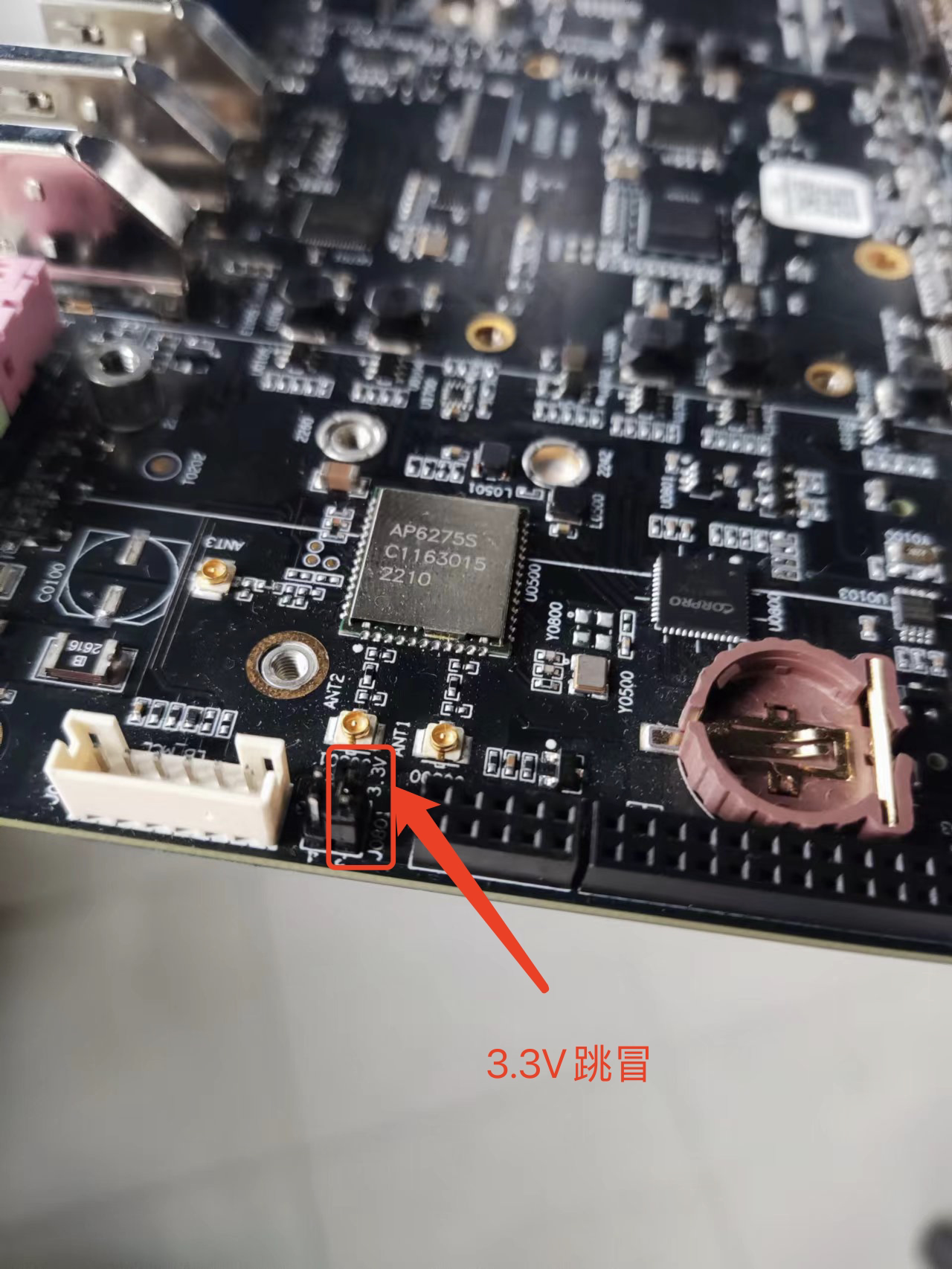
Check the 3.3V Jumper